Within this tutorial, we are going to optimize 3D meshes with the compact command, this time however we will dive a bit deeper into the settings affecting the reduction of the meshes. This process is sometimes also referred to as Mesh Reduction or as Mesh Decimation. The latter term, decimation, is used within the RapidCompact CLI options and settings.
In addition, we will also explore another method for simplifying a 3D mesh using remeshing. The difference between decimation and remeshing is quite profound: While the former operates on the original input geometry and thus can be quite limited if the input geometry is flawed or otherwise complex, the latter is independent of any flaws of the input topology and re-creates the mesh completely.
RapidCompact CLI has several settings that can be used to control the decimation process:
Mesh Decimation
| Name | Type | Default | Valid Range | Quick Description |
|---|---|---|---|---|
| decimation:collapseUnconnectedVertices | Flag | true | {true, false} | switches collapsing of nearby, unconnected vertices on/off |
| decimation:preserveCommonMeshBorders | Flag | true | {true, false} | preserves borders (vertices) common between meshes |
| decimation:preserveMaterialBorders | Flag | false | {true, false} | preserves mesh material borders during decimation |
| decimation:preserveNormals | Flag | false | {true, false} | preserves vertex normals during decimation |
| decimation:preserveTiledUVs | Flag | false | {true, false} | preserves repeating texture coordinates during decimation |
| decimation:preserveTopology | Flag | false | {true, false} | preserves topological features like holes during decimation |
| decimation:preserveUVs | Flag | false | {true, false} | preserves texture coordinates during decimation |
| decimation:recomputeNormals | Flag | true | {true, false} | switches computation of new normals after decimation on or off |
| decimation:boundaryPreservationFactor | Real | 0.5 | {0 .. 1} | factor to steer preservation of boundaries during decimation |
| decimation:collapseDistanceThreshold | Real | 0.005 | {0 .. 0.10000000000000001} | threshold w.r.t BBox diagonal for collapsing nearby vertices |
| decimation:probQuadricStddev | Real | 0 | {0 .. inf} | standard deviation for probabilisitc quadrics |
| decimation:tiledUVThreshold | Real | 1.5 | {1 .. inf} | UV extent after which a UV channel is considered repeating (= tiling texture) |
| decimation:defaultTarget | String | f:20000 | target parameter for decimation during compact | |
| decimation:method | String | quadric | {'quadric', 'edgeLength'} | method to be used for decimation |
decimation:preserveUVs and decimation:preserveMaterialBorders are working very well together if the texture coordinates and material coverage should be preserved while also simplifying the geometry. You can read more about this topic here.
decimation:defaultTarget is the main setting related to decimation targets and is used when decimation is indirectly invoked using the compact (-c) operation.
decimation:method, can be used to specify which method should be used for decimation. There are two methods available: "quadric" (the default) and "edgeLength".
With decimation:preserveTopology, you can turn the strict preservation of topological features on or off.
The three settings, decimation:collapseUnconnectedVertices, decimation:boundaryPreservationFactor and decimation:collapseDistanceThreshold can be used to control (and enable / disable) the collapsing of unconnected, closeby vertices and, for the boundary preservation, to specify how strongly boundaries should be preserved during the decimation process. We will explore all of the settings by example within the following paragraphs.
Note that, within this tutorial, we will use the --compact operation (which also does some other things apart from decimating the mesh).
To get started with the decimation functionality of RapidCompact CLI, we will use a simple example mesh of a scanned nefertiti bust, which you can download here.
This mesh has 1,5 million faces, which makes it a medium-sized data set. Although it could already be used like this for many visualization applications, some might require a variant that consists of less triangles, for example for quick rendering in a VR or game context. Another reason for generating a simplified version might be the reduction of bandwidth which is needed to transmit this mesh over a network (for example, for online presentation). Within the baking tutorial, we will see how to generate different texture maps, applied on the low-resolution asset, can help us to faithfully preserve the details of the high-resolution original. However, within this tutorial, we will just simplify the 3D geometry of the mesh.
To generate a simplified version of the nefertiti mesh, you can use the following command line:
rpdx -i nefertiti.ply -c 2000 -e nefertiti-lowpoly.obj
This command will generate an OBJ file entitled nefertiti-lowpoly.obj, containing the simplified version of the input mesh. The compact command, here abbreviated using the shorthand version c, accepts several parameters. By default, a number is interpreted as a target amount of vertices. However, you can also specify a target amount of faces a target percentage of vertices or faces, a screen size target or even a MB target. Examples:
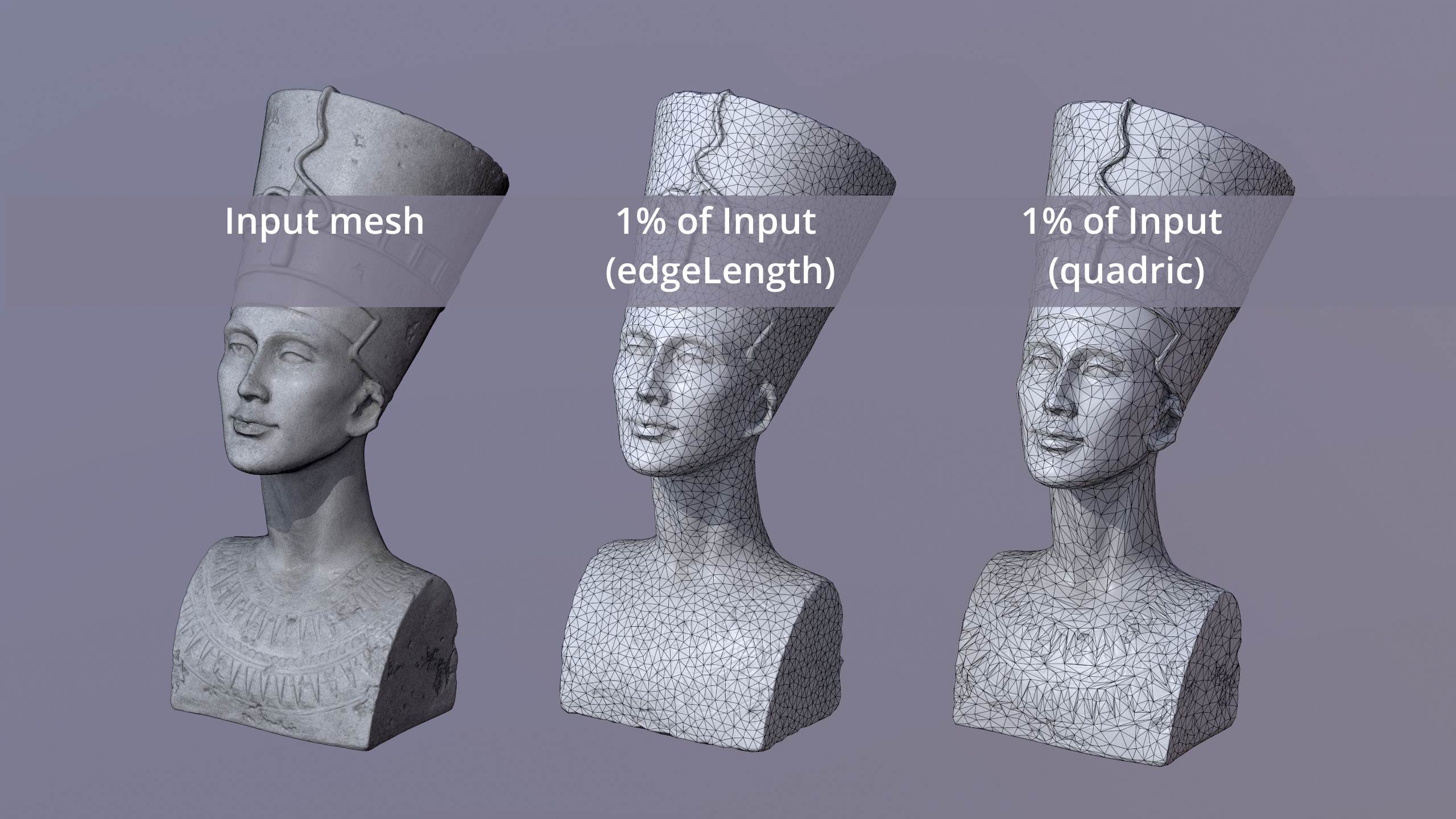
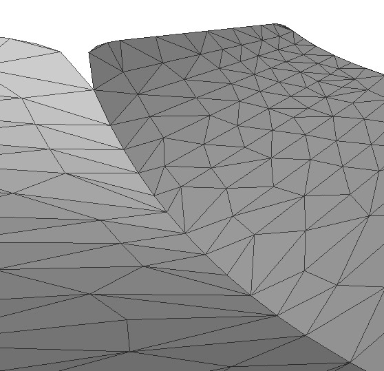
The method used by default is the quadric method. There is also another one, which is entitled edgeLength. The edgeLength method is more simple and hence slightly faster, and it produces a resulting mesh where the triangles have a very regular distribution, which can be beneficial for some applications. However, the quadric method will be preferred in most cases, as it preserves features relatively well. The following figure shows a comparison of the results, using a strong simplification to 1% of the original vertices:
Now that we have studied the basics about simplifying a mesh with the RapidCompact CLI we will have a look at some functions for specific simplification use-cases by adding advanced commands:
A common artifact arising during simplification is deformation of open mesh boundaries. To experience this by example, we will use this model of a teapot.
To see what happens when a mesh is simplified without special constraints for the boundaries, set decimation:boundaryPreservationFactor to zero and run this command:
rpdx -i teapot.obj -c 500 -e reduced.obj
This will produce a reduced teapot that looks like this:
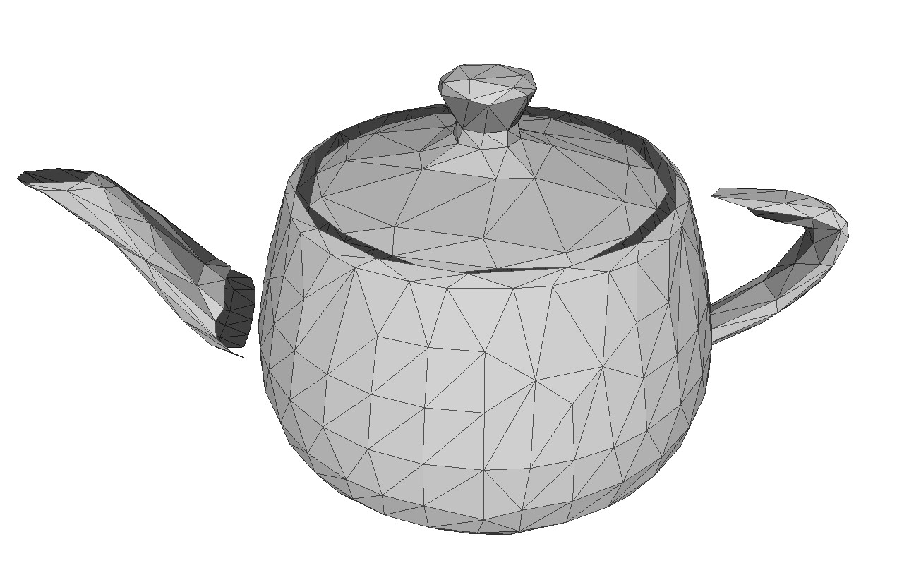
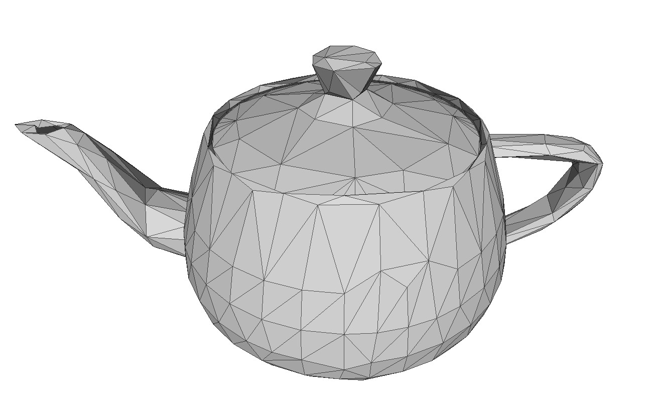
Not very satisfying, you would probably say. What looks especially ugly and "wrong" are the displaced boundary vertices, leading to the handle and spout floating somewhere in the air, instead of being connected to the body of the teapot. The reason for this is that the teapot's spout and handle were actually separate pieces that are not connected to the body's vertices within the original model. In such cases, it helps to apply some special constraints for the mesh boundaries. Setting decimation:boundaryPreservationFactor to 0.5 gives a much nicer result:
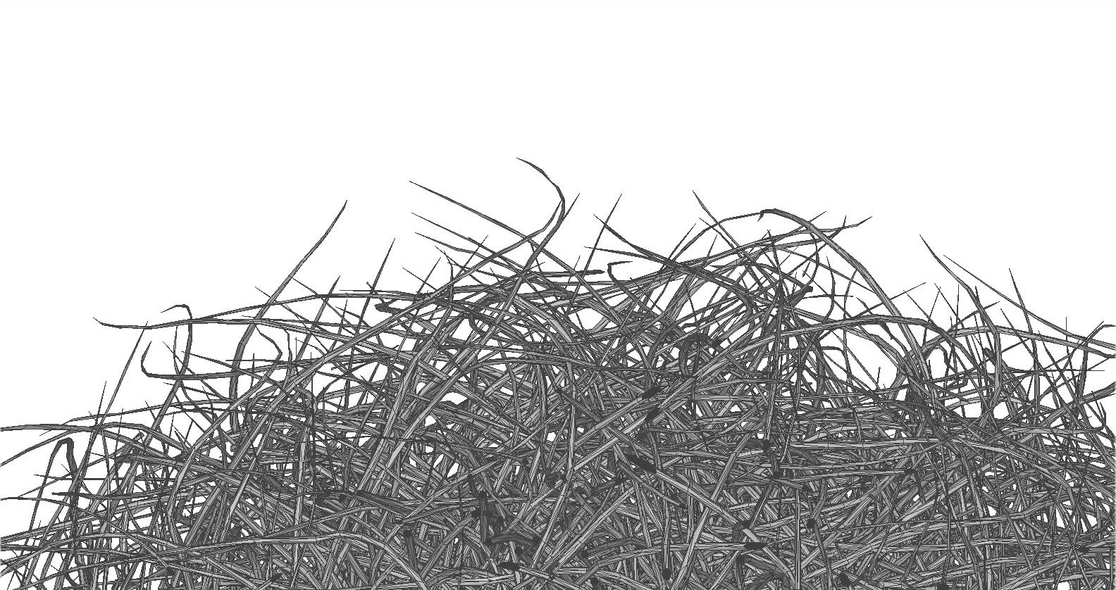
For most visualization applications, we obtain good result by decimating input meshes without caring about the topology of the result. This allows the simplification algorithm to remove small holes or handles, for example, when creating a low-poly approximation of the input mesh. However, for certain applications and certain input models, we may want to preserve the exact topology of the input, meaning: holes should never be closed, and handles and different surface parts should never be merged. Regarding the visual quality of the output, topology preservation can especially be useful when dealing with geometric details like fine strands. Here's an example mesh which we can use for a small test (original Hairball model courtesy of NVIDIA research): hairball.ply A detail view on it looks like the following:
We can simplify this input model to 25% of its faces, using the following command:
rpdx -i hairball.ply -c f:25% -e result.ply
The result will look like the following:
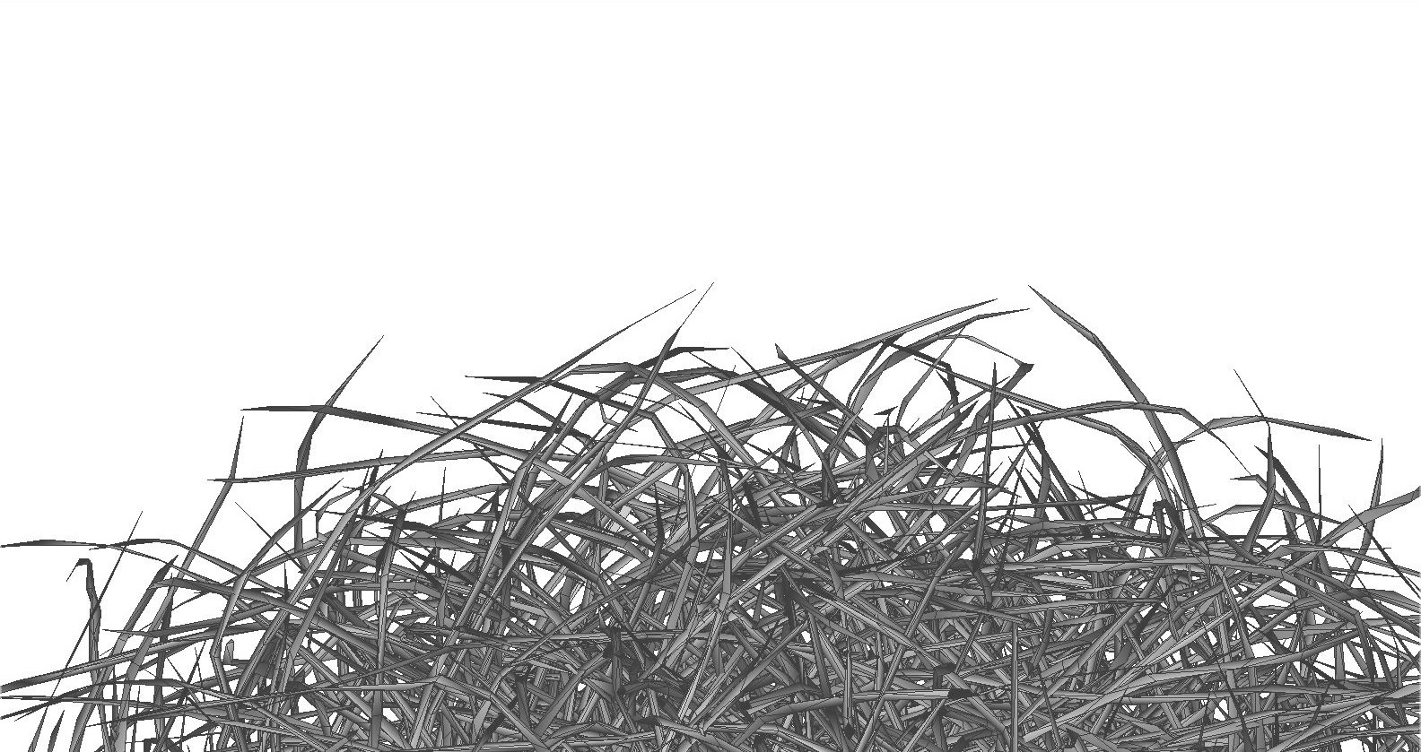
As can be seen, the simplification took away some of the tips of the strands. It also allows, in principle, that the vertices of separate strands will get merged together, or that strands will get split up into multiple pieces possibly floating in the air, in other words: it allows for changes of the mesh topology. RapidCompact can be configured to forbid such changes, using the flag decimation:preserveTopology:
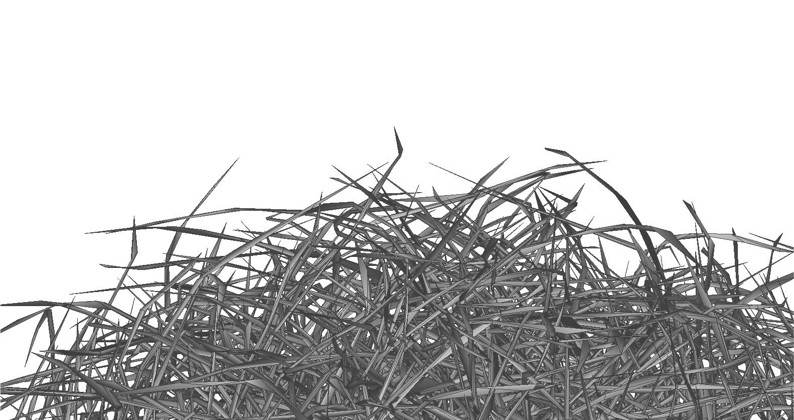
rpdx -i hairball.ply -s decimation:preserveTopology true -c f:25% -e result-pt.ply
In this case, this will lead to a much better preservation of the many single strands of the hairball, and to a better preservation of its "volume", as no strands will be merged or torn apart by the simplification:
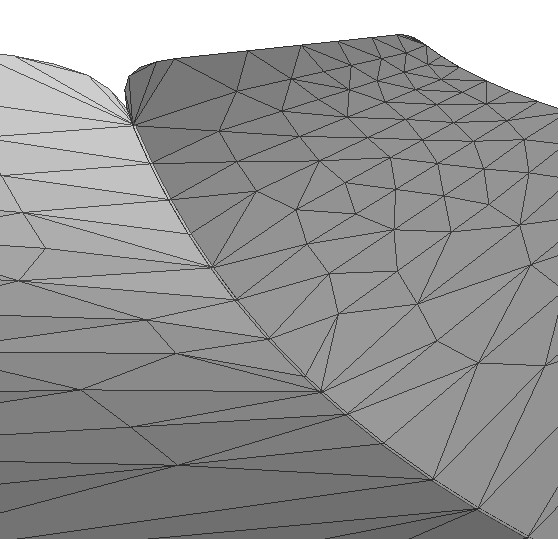
For certain meshes, especially those generated through CAD, the surface may be composed out of several parts, or patches. Such patches are often not explicitly connected at their boundaries, but instead vertex positions of two neighboring patch boundaries will simply match. Without boundary preservation, we might run into problems here, as those boundaries may "crack up" (compare the example of the teapot shown above). In such cases, we can also handle the problem differently: instead of preserving boundaries (using decimation:boundaryPreservationFactor), we can also weld them together. This effectively means that we are allowing the simplification method to merge nearby vertices, regardless of whether they belong to the same surface patch or not. This can be done using the setting decimation:collapseDistanceThreshold, which is a value relative to the model's bounding box diagonal. For this simple example mesh of two bent sheets, setting decimation:collapseDistanceThreshold to zero and performing decimation to 500 vertices will produce a result like this at the boundaries between both patches:
In constrast, by setting decimation:collapseDistanceThreshold to 0.1, we obtain a result where the boundary vertices of both sheets have been "welded" together:
Sometimes Mesh Decimation as a method for simplifying Geometry can lead to artifacts or unwanted distortions on the low res output mesh. This is true with models resembling real-world wicker surfaces or complex apparel assets with stiching and other fine "micro-geometry" details. In 3D graphics there is a technique offen referred to as remeshing which in combination with normal map baking can successfully reduce substantial amounts of geometry for these complex meshes without loosing too much of visual fidelity.
Within RapidCompact remeshing is always working in conjunction with decimation. The first setting introduced is a boolean, which enables the remeshing process. The remeshing process will be initiated within the compact operation, but before the actual mesh decimation. Thus the initial input for decimation is being replaced with a remeshed version of the input first. In case no decimation is desired, a face or vertex target of 100% can be utilized.
The second setting is the remeshing resolution which steers the desired level of high res density of the remeshing process. The higher the resolution (1-11), the more dense the initial remeshing and the more geometrical detail can be captured. However this does not always mean a higher resolution is better, as we will explore in the tutorials further below. The default of 0 is the automatic mode which sets the resolution according to the given remeshing method (10 for the default method voxelization and 7 for the method shrinkwrap_mesh).
The third setting switches between the two available remeshing methods: voxelization and shrinkwrap_mesh. We recommend each method for a specific remeshing workflow as laid out in the tutorials below.
| Name | Type | Default | Valid Range | Quick Description |
|---|---|---|---|---|
| remeshing:enabled | Flag | false | {true, false} | enables remeshing during compact |
| remeshing:resolution | Int | 0 | {1 .. 11} | maximum tree depth |
| remeshing:method | String | voxelization | {'voxelization', 'shrinkwrap_mesh'} | specify the type of remeshing to perform before decimation |
In the following we will look at the default voxelization method and how it can help within two example scenarios:
Within this tutorial we will explore the latter example and how voxelization remeshing can help to obtain the best result possible within a given face count budget.
To demonstrate the remeshing functionality, we will first use a specific complex example mesh of a Digital Fashion item, which you can download here.
This 3D model is quite complex as multiple unconnected mesh parts with multiple layers are utilized. Digital Fashion assets are usually set-up in such a manner due to the complex design workflow startng with cutting patterns instead of meshes.
In order to see what happens with an ordinary decimation operation, please go ahead and use the following command:
rpdx -i PufferJacket_thick_two-color.glb -c -e decimated.glb
As you will see in the next section further below, the resulting optimized output file has multiple issues mostly related to the complexity of the input geometry.
Now use the following tweaked command to enable remeshing before we start the exact same decimation process to the default decimation target of 20.000 faces.
rpdx -i PufferJacket_thick_two-color.glb -s remeshing:enabled true -c -e remeshed.glb
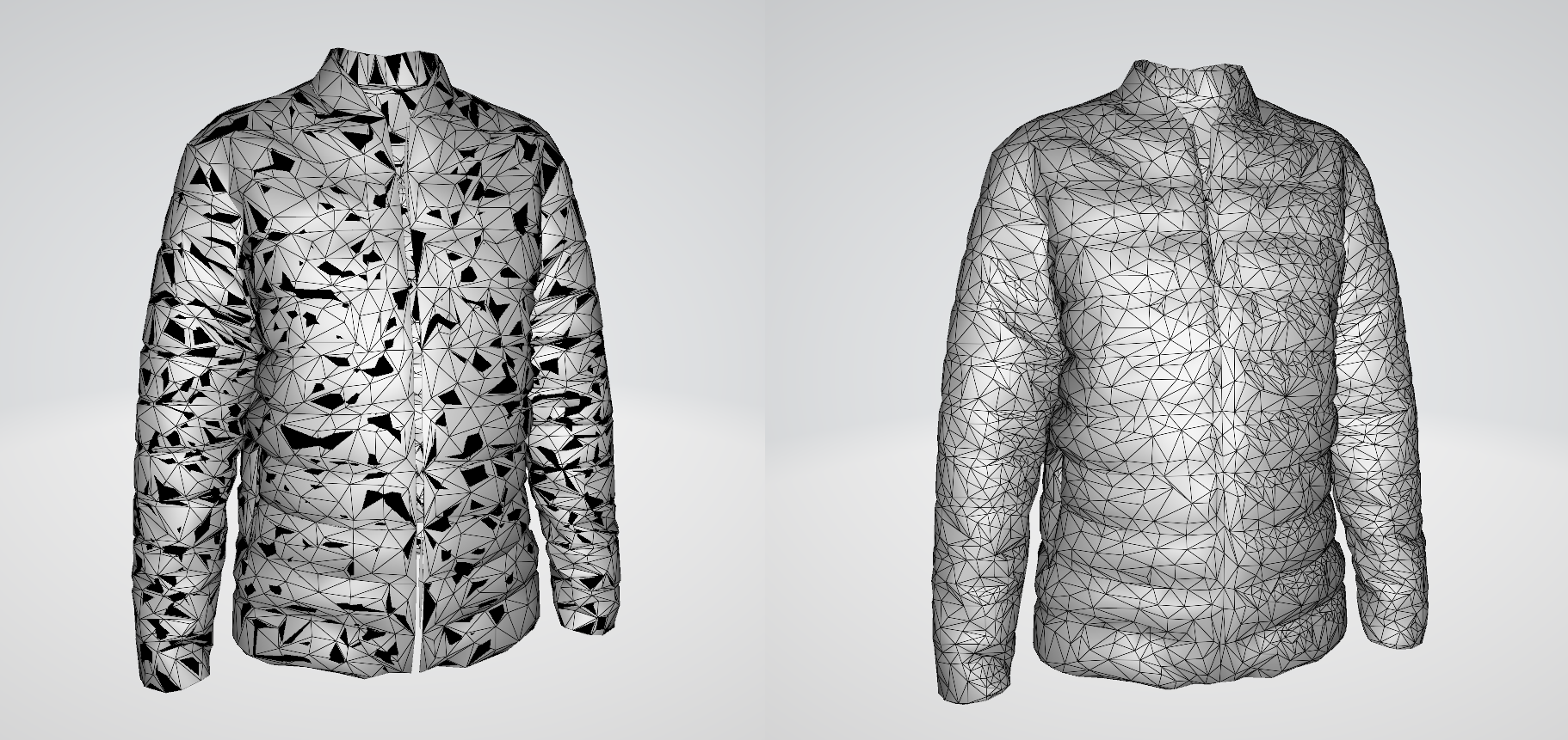
Next, as we have both outputs, let us compare the optimized output models and especially their meshes below:
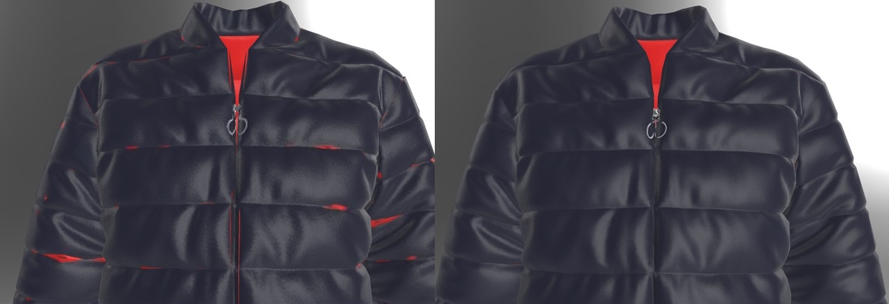
When comparing the results from the command operations above, we can identify multiple issues with the decimated variant (left):
These issues do not exist with the variant utilizing the remeshing functionality (right). The reason for this is, that remeshing created an entirely new single watertight geometry, which is much more desirable input for any mesh decimation process.
Comparing the geometry within an isolated view, we can observe additional helpful traits of the remeshing process:
There are cases where even the voxelization remeshing method can not produce good results while reducing geometry substantially. This is especially the case with meshes resembling wicker or certain types of baskets and in general surfaces with lots of topological holes. These types of meshes could be remeshed with a very high resolution but would ultimately fail to the same constraints as the standard decimation when reducing geometry substantially.
There is however another remeshing method which can help with wrapping new geometry around these surfaces. Within the RapidCompact CLI this method is called shrinkwrap_mesh. This method can easily create watertight new surfaces by wrapping the new geometry around the original mesh shape. In addition, in order to create results which most resemble the input data while having a very simplified geometry, we can utilize the baking setting topologicalHolesToAlpha which helps to re-create a similar look of the originally topological holes but achieved with an alpha mask texture map. In the following we will explore the required settings and will look at a simple example model.
| Name | Type | Default | Valid Range | Quick Description |
|---|---|---|---|---|
| baking:topologicalHolesToAlpha | Flag | false | {true, false} | capture areas where the corresponding source surface was not found on an alpha mask |
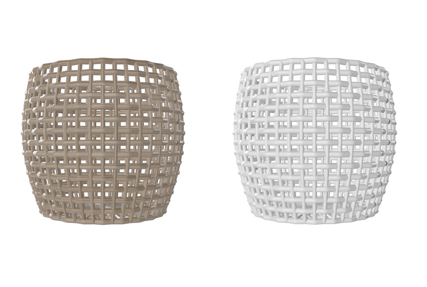
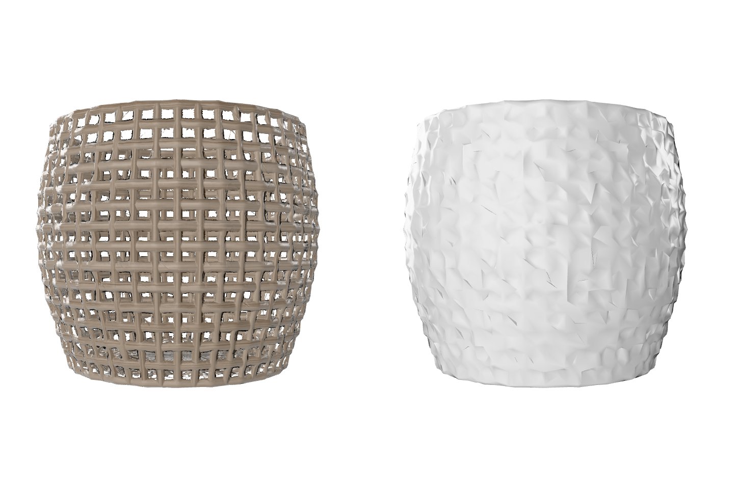
For this tutorial we will use this wicker basket model generated within a DCC tool. Download the file here. See below a simple rendering comparing the shaded view and the blank material view. The latter is better suited to compare the resulting raw geometrical surfaces with each other.
Let's start with a first attempt using the shrinkwrap_mesh method as well as the alpha baking feature:
    rpdx -i DGG_CaneBasket_PBR-material.glb -s remeshing:enabled true -s remeshing:method shrinkwrap_mesh -s baking:topologicalHolesToAlpha true
	-c -e DGG_CaneBasket_PBR-material_remeshed.glb
We can also write these settings into config file, download it here. Going forward, we will use this configuration file in combination with additional settings.
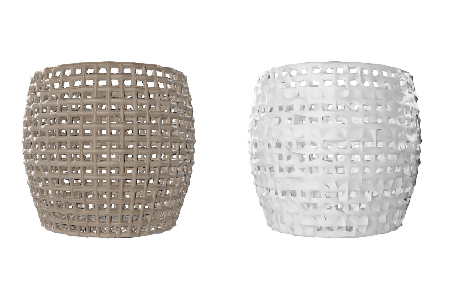
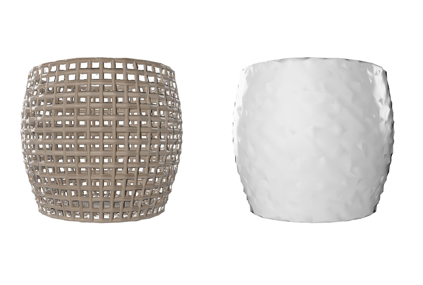
As you can see, the remeshing resolution was not low enough to properly wrap around the input surface. Let us use a lower remeshing resolution and decimation target in order to achieve a watertight mesh.
Second attempt using the configuration from before and changing the remeshing resolution as well as adding a 10k decimation target (instead of default 20k).
    rpdx -i DGG_CaneBasket_PBR-material.glb --read_config remeshing_config.json  -s remeshing:resolution 6 -c f:10000
	-e DGG_CaneBasket_PBR-material_remeshed-lowres.glb
As you can see, the remeshed surface is much better and now closed. However, note the subtle normal issues. This is due to the RapidCompact default normalHardAngle of 60 which usually works great for all kinds of assets. However with this particular remeshing method we want to set it to 180 in order to achieve all soft angles.
Adjusting the mesh normal angle for better results.
    rpdx -i DGG_CaneBasket_PBR-material.glb --read_config remeshing_config.json -s remeshing:resolution 6 -c f:10000
	-s general:normalsHardAngleDeg 180 -c -e DGG_CaneBasket_PBR-material_remeshed-lowres-adusted.glb
Looking at results
As you can see, the mesh normals are now all averaged resulting in a better surface for the shrink-wrapped output.
The next tutorial will focuss on additonal decimation constraints such as preserving the UV coordinates.